
The problem
According to a study conducted by Flight Safety Foundation (FSF) in 2007, it was estimated that 27,000 ramp accidents and incidents occurred worldwide every year, resulting in an estimated cost of $5 billion to the airline industry. Initial analyses of the data collected at the time indicated that contact between airplanes and ground-service equipment—baggage loaders, air bridges, catering vehicles, fuel trucks, etc.—accounted for more than 80 per cent of these ramp accidents/incidents.
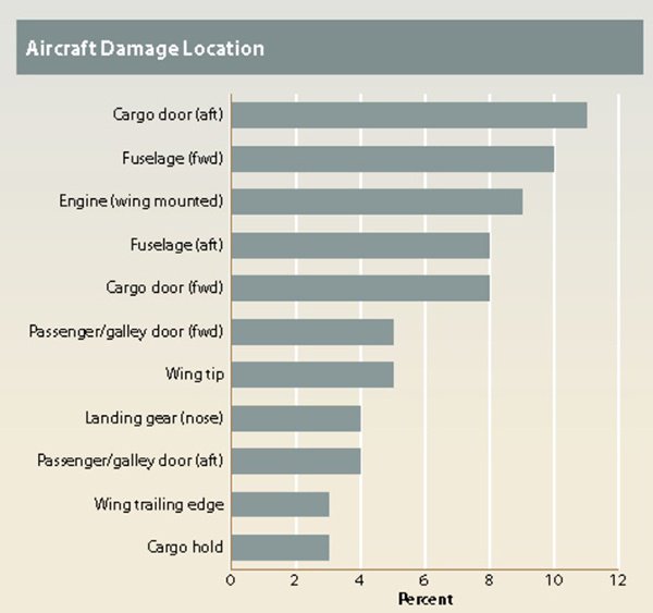
Figure 1. Location of damage by ground support equipment (source: FSF).
Additionally, the aircraft damage caused by bird strikes and lighting strikes also results in significant disruption and additional cost for airlines. In addition, the direct cost of repairing damages is, in some cases, only a small part of the overall cost. Airlines incur considerable indirect costs, particularly due to delays, which result in compensation costs driven by consumer protection legislation such as EC261 in the EU. Many damage prevention strategies have been put in place to limit the occurrence of aircraft damage—however, damage events do still happen and the recovery process to return an aircraft to service in an expedient manner is of high importance to operators.
Repair activity to recover from aircraft damage is complicated and involves a number of steps, including accurate damage assessment. The current methods have various sources of error; from the use of the tools involved to the human visual inspection element.
The study
I conducted a research project over the last year as part of my studies at Cranfield University to obtain the MSc Airworthiness award. Here, I would like to share an overview of this study and the results.
The study examined the limitations of current aircraft damage assessment activity. The use of dimensional inspection equipment, including precision hand tools, was critically reviewed. The limitations of humans carrying out this activity were also examined and the benefits and limitations of using 3D scanning techniques were explored.
The study was conducted in three phases: a survey of engineers carrying out damage assessment, an experiment comparing recorded aircraft damage to 3D scan derived measurement data and a visual inspection experiment.
The survey
A questionnaire was designed and used to collect data from certifying engineers within an approved maintenance organisation, which is also part of an operator. A total of 27 responses were received. The organisation sampled has a younger workforce than the UK CAA average by some eight years.
67 per cent of engineers stated that they carried out damage assessment activity within the last two years—however, 33 per cent of engineers had never carried out any damage assessment. 89 per cent of those surveyed were also found to have never had any specific SRM or damage assessment training. While this is not a regulatory requirement, it is an excellent way of improving skills in an activity that is infrequent for some engineers.
The results also indicated issues with some engineers not having regular eye tests (e.g. every two years) as expected.
The visual measurement and 3D scanning experiments
The results of the research indicate a significant problem with reproducibility when examining an engineer’s ability to assess aircraft damage. The problem of identification of a reference plane, and the difficulty in use of precision hand tools with an airframe surface were identified as contributing factors.
Standard distributions of dimensional measurement responses indicated an expected response from a sampled group—there was little effect from skew or outliers to the measurements across the group sampled.
There was an observed tendency to underestimate large dimensions (width and height) and a tendency to overestimate the small (depth) dimensional measurement when compared to the reference values obtained by 3D scanning.
Where 3D scanning was carried out on existing damaged articles across the operator’s fleet, the three selected articles all were found to be out of compliance with the approved data set limits.
Depth measurements were found to be the most reliable when the aircraft tech log values were compared to the 3D scan model measured dimensions. The larger measurements of width and height were found to demonstrate the most deviation from the 3D scanned values.
One of the largest identified issues with carrying out damage assessment on an aircraft surface is that of the reference plane. Where a surface is curved it can be very difficult to accurately measure where the surface used to be pre-damage to take measurements from. Many surfaces on an aircraft are also compound curved, making the identification of the reference plane even more difficult.
3D scanning was found to offer the benefit of an easily producible reference plane, and ability to measure damage with sub-millimetre accuracy, as well as quickly identifying surface features that are not readily detectable by an inspector through visual inspection.
The data recording ability of a 3D scan of aircraft damage offers part M organisations much more data than the currently used methods, where an inspector records damage width, height and depth as appropriate. 3D models of damage allow an organisation to take many bespoke measurements as required and maintains a much richer data set of the fleet damage.
3D scanning is a broad term and can accommodate a number of methods and devices. For aircraft damage assessment the use of 3D handheld structured light/laser scanners is the most suitable for the application of damage assessment in a dynamic environment such as aircraft maintenance, particularly on the line.
Visual inspection weaknesses were identified in literature review and confirmed in the visual inspection experiment, and further in the 3D scan comparison experiment. The ability of an inspector to accurately identify the limits of any damage article is limited by their ability to accurately perceive deviations of as little as 0.5mm from a reference plane that is as best as they can fit using hand tools or, in some cases, only estimated visually.
3D scanners can deliver sub one-tenth of a millimetre resolution and accuracy, but ultimately it is the ease at which their scans can produce a perfect reference surface model from which to measure from, and the ability of software to produce easily readable surface topographies, that delivers the greatest benefit to the inspector. Using 3D scanning techniques, it is easy to identify surface deviations of less than 0.5mm, and this makes the identification of damage features very easy where humans are so clearly limited in this respect.
The full version of this article was originally published in Airworthiness Matters 2018 (International Federation of Airworthiness (IFA)).
Phil Mumford is an Airworthiness MSc graduate.